ADM1029
http://onsemi.com
18
It is recommended that the minimum PWM duty cycle be
set to 33% (0x05). This has been determined to be the lowest
PWM duty cycle that most fans will run reliably at. Note that
the PWM duty cycle values programmed in to these registers
also define the PWM duty cycle that the fans will turn on at,
in Automatic Fan Speed Control Mode. It is recommended
that after power-up, the PWM duty cycle is set to 33% before
enabling Automatic Fan Speed Control.
Thermal Trip Mode
The ADM1029 can thermally trip the fan(s) for simple
on/off fan control, or 2-speed fan control. For example, a fan
can be programmed to run at 33% duty cycle. If the
temperature exceeds the high temperature limit set for that
temperature channel, the fan can automatically trip and run
at Alarm Speed. The fan will continue to run at Alarm Speed
even if the temperature error condition subsides, until the
Latch Temp Fault bit (Bit 7 of the Temp x Fault Action Reg)
is cleared in software by writing a 0 to it. To configure Fan 1
normally, run at 33% but to thermally trip to Alarm Speed
for a Remote 2 measured temperature of 70癈, set up the
following registers:
1. Configure the normal PWM duty cycle for Fan 1
to 33%.
Fan 1 MinimumAlarm Speed Reg (0x60) + 0xF5
2. Set the Remote 2 High Temperature Limit = 70癈.
Remote 2 Temp High Limit Reg (0x92) + 0x46
3. Configure Alarm Speed on Overtemperature
function for Remote 2 Temperature channel.
Set Bit 1 of Temp 2 Fault Action Reg (0x42)
4. Enable Fan 1 to be controlled by Remote 2
Temperature.
Set Bit 0 of Temp 2 Cooling Action Reg (0x4A)
Once the fan thermally trips to Alarm Speed, it will
continue to run at Alarm Speed until the temperature drops
below the High Temperature Limit and the Latch Temp Fault
bit (Bit 7 of the Temp 2 Fault Action Reg) is cleared to 0.
Event Latch Bits
Certain events that occur will cause latch bits to be set in
various registers on the ADM1029. Once a latch bit is set, it
will need to be cleared by software for the system to return
to normal operation. To detect if a latch bit has been set, the
INT
pin can be used to signal a latch event to the system
supervisor. Alternatively, the Status Registers can be polled
periodically, and any latch bits that are set can be cleared.
The events that cause latch bits to be set are:
1. Thermal Events. If the fan is run at Alarm Speed
on Overtemperature or Undertemperature, this will
set the Latch Temp Fault bit (Bit 7 of the
Temp x Fault Action Registers 0x400x42).
2. Missing Fan. If a fan is missing, i.e., has been
unplugged, the Missing Latch bit (Bit 1 of
Fan x Status Registers) is set.
3. Hotplugged Fan. If a new fan is inserted into the
system, Bit 7 (Hotplug Latch bit) of the
Fan x Status Register is set.
4. FAULT Asserted. If the fan becomes stuck and its
FAULT output asserts low, Bit 2 (Fault Latch bit)
of the Fan x Status register is set.
5. TACH Failure. If the fan runs underspeed or
becomes stuck, then Bit 6 (Tach Fault Latch Bit)
of the Fan x Status Register is set.
Automatic Fan Speed Control
The ADM1029 has a local temperature channel and two
remote temperature channels, which may be connected to an
on-chip diode-connected transistor on a CPU or a
general-purpose discrete transistor. These three temperature
channels may be used as the basis for an automatic fan speed
control loop to drive fans using Pulsewidth Modulation
(PWM).
How Does The Control Loop Work?
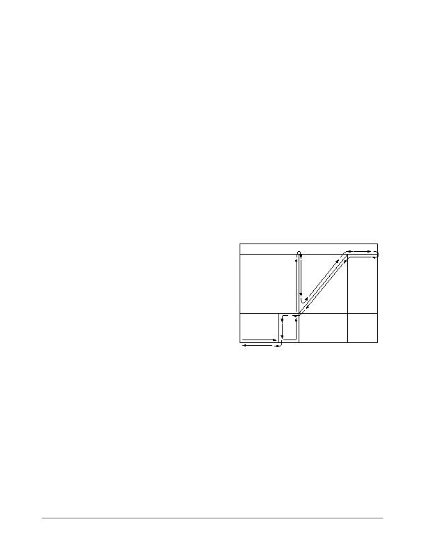
The Automatic Fan Speed Control Loop is shown in
Figure 29.
Figure 29. Automatic Fan Speed Control
TEMPERATURE
T
MIN
MIN
MAX
T
MAX
= T
MIN
+ T
RANGE
SPIN UP FOR 2 SECONDS
In order for the fan speed control loop to work, certain
loop parameters need to be programmed in to the device:
1. T
MIN
. This is the temperature at which a fan
should switch on and run at minimum speed. The
fan will only turn on once the temperature being
measured rises above the T
MIN
value programmed.
The fan will spin up for a predetermined time
(default = 2 secs). See Fan Spin-up section for
more details.
2. T
RANGE
. This will be the temperature range over
which the ADM1029 will automatically adjust fan
speed. As the temperature increases beyond T
MIN
,
the PWM duty cycle will be increased accordingly.
发布紧急采购,3分钟左右您将得到回复。
相关PDF资料
ADM1030ARQZ-RL7
IC SNSR TEMP/FAN PWM CTRL 16QSOP
ADM1032ARZ-REEL
IC TEMP MONITOR 85DEG 8SOIC
ADM1033ARQZ-RL7
IC THERM/FAN SPEED CTLR 16-QSOP
ADM1034ARQZ-REEL
IC THERM/FAN SPEED CTRLR 16-QSOP
ADN8810ACPZ-REEL7
IC CURRENT SOURCE(12BIT) 24LFCSP
ADP2140ACPZ3328R7
IC REG DL BCK/LINEAR 10LFCSP
ADP5022ACBZ-6-R7
IC REG TRPL BCK/LINEAR 16WLCSP
ADP5041ACPZ-1-R7
IC REG TRPL BCK/LINEAR 20-LFCSP
相关代理商/技术参数
ADM1030
制造商:AD 制造商全称:Analog Devices 功能描述:Intelligent Temperature Monitor and PWM Fan Controller
ADM1030ARQ
功能描述:IC SNSR TEMP/FAN PWM CTRL 16QSOP RoHS:否 类别:集成电路 (IC) >> PMIC - 热管理 系列:- 标准包装:1 系列:- 功能:温度监控系统(传感器) 传感器类型:内部和外部 感应温度:-40°C ~ 125°C,外部传感器 精确度:±2.5°C 本地(最大值),±5°C 远程(最大值) 拓扑:ADC,比较器,寄存器库 输出类型:2 线 SMBus? 输出警报:无 输出风扇:无 电源电压:2.7 V ~ 5.5 V 工作温度:-40°C ~ 125°C 安装类型:表面贴装 封装/外壳:SOT-23-8 供应商设备封装:SOT-23-8 包装:Digi-Reel® 其它名称:296-22675-6
ADM1030ARQ-REEL
功能描述:IC SNSR TEMP/FAN PWM CTRL 16QSOP RoHS:否 类别:集成电路 (IC) >> PMIC - 热管理 系列:- 标准包装:1 系列:- 功能:温度监控系统(传感器) 传感器类型:内部和外部 感应温度:-40°C ~ 125°C,外部传感器 精确度:±2.5°C 本地(最大值),±5°C 远程(最大值) 拓扑:ADC,比较器,寄存器库 输出类型:2 线 SMBus? 输出警报:无 输出风扇:无 电源电压:2.7 V ~ 5.5 V 工作温度:-40°C ~ 125°C 安装类型:表面贴装 封装/外壳:SOT-23-8 供应商设备封装:SOT-23-8 包装:Digi-Reel® 其它名称:296-22675-6
ADM1030ARQ-REEL7
功能描述:IC SNSR TEMP/FAN PWM CTRL 16QSOP RoHS:否 类别:集成电路 (IC) >> PMIC - 热管理 系列:- 标准包装:1 系列:- 功能:温度监控系统(传感器) 传感器类型:内部和外部 感应温度:-40°C ~ 125°C,外部传感器 精确度:±2.5°C 本地(最大值),±5°C 远程(最大值) 拓扑:ADC,比较器,寄存器库 输出类型:2 线 SMBus? 输出警报:无 输出风扇:无 电源电压:2.7 V ~ 5.5 V 工作温度:-40°C ~ 125°C 安装类型:表面贴装 封装/外壳:SOT-23-8 供应商设备封装:SOT-23-8 包装:Digi-Reel® 其它名称:296-22675-6
ADM1030ARQZ
功能描述:马达/运动/点火控制器和驱动器 TDM & PWM FAN CNTRLRS IC RoHS:否 制造商:STMicroelectronics 产品:Stepper Motor Controllers / Drivers 类型:2 Phase Stepper Motor Driver 工作电源电压:8 V to 45 V 电源电流:0.5 mA 工作温度:- 25 C to + 125 C 安装风格:SMD/SMT 封装 / 箱体:HTSSOP-28 封装:Tube
ADM1030ARQZ-REEL
功能描述:板上安装温度传感器 TDM PWM FAN CTRLRS IC RoHS:否 制造商:Omron Electronics 输出类型:Digital 配置: 准确性:+/- 1.5 C, +/- 3 C 温度阈值: 数字输出 - 总线接口:2-Wire, I2C, SMBus 电源电压-最大:5.5 V 电源电压-最小:4.5 V 最大工作温度:+ 50 C 最小工作温度:0 C 关闭: 安装风格: 封装 / 箱体: 设备功能:Temperature and Humidity Sensor
ADM1030ARQZ-REEL7
功能描述:IC SNSR TEMP/FAN PWM CTRL 16QSOP RoHS:是 类别:集成电路 (IC) >> PMIC - 热管理 系列:- 标准包装:1 系列:- 功能:温度监控系统(传感器) 传感器类型:内部和外部 感应温度:-40°C ~ 125°C,外部传感器 精确度:±2.5°C 本地(最大值),±5°C 远程(最大值) 拓扑:ADC,比较器,寄存器库 输出类型:2 线 SMBus? 输出警报:无 输出风扇:无 电源电压:2.7 V ~ 5.5 V 工作温度:-40°C ~ 125°C 安装类型:表面贴装 封装/外壳:SOT-23-8 供应商设备封装:SOT-23-8 包装:Digi-Reel® 其它名称:296-22675-6
ADM1030ARQZ-RL7
功能描述:IC SNSR TEMP/FAN PWM CTRL 16QSOP RoHS:是 类别:集成电路 (IC) >> PMIC - 热管理 系列:- 标准包装:1 系列:- 功能:温度监控系统(传感器) 传感器类型:内部和外部 感应温度:-40°C ~ 125°C,外部传感器 精确度:±2.5°C 本地(最大值),±5°C 远程(最大值) 拓扑:ADC,比较器,寄存器库 输出类型:2 线 SMBus? 输出警报:无 输出风扇:无 电源电压:2.7 V ~ 5.5 V 工作温度:-40°C ~ 125°C 安装类型:表面贴装 封装/外壳:SOT-23-8 供应商设备封装:SOT-23-8 包装:Digi-Reel® 其它名称:296-22675-6
